Contact Info
Monday through Friday, 8am – 8pm EST.
1800 Shames Drive
Westbury, NY 11590
(877) 346–3837 or 1–877–EIMETER
EIGTechSupport@Hubbell.Com
Shark® Series
Our system is a 277/480V Wye system. Can I use it to power my meter? I have a D2 option control power.
The Power supply option D2 has a range of 90-265 V AC or 100-370 V DC so 277 V AC is about 5% higher than the rated voltage. When used at this higher voltage and in prolonged period of time will have great effect on the power supply that may cause the meter to break down early. It is recommended to seek an alternative 120 V AC regular plug or use a control power transformer to step down the voltage from 480 V to 120 V.
I am only using the meter for current measurement only and I have my CTs in place but the meter is not reading even if I have my load.
At least one voltage input with a minimum 20 V AC must be connected in it to work. This is “bias” voltage and is necessary for the meter to work properly in CT measurement mode only.
Can I use the meter for single phase application? How do I wire it for single phase?
Yes the meter can be used for any single phase application (2 wire or 3 wire). The manual already have an example of the wiring diagram for Dual phase (3 wire) and single phase (2 wire). Please see pages 4-9 to 4-10 for the diagram.
On other power meter electrical diagram, the CTs are tied up at the Lo side and connected to ground. But the Shark manual doesn’t show any Lo side being tied up together to ground. Should we tie it up to ground?
Electrical diagrams on our manual show Low side of the CTs tied up together and connected to ground using CT Shorting Block. The grounding of current transformers is important for safety.
Can I use the infrared port of my laptop to connect to the meter via IrDA port?
No. You will need our CAB6490 IrDA dongle to do that. The dongle comes already with Windows 7 compatible driver and so driver installation is automatic. The important feature that makes it ‘Standard Modem Over Ir Link” is the most important feature for it to connect seamlessly to the meter using our CommunicatorPQA® software.
Where do I read the peak demand in the front display?
Press the scroll down button to go to “W/VAR/PF” screen and then press the arrow right button once to lit the “MAX” LED on the left side. The phase A reading is your Max Demand Watts reading or Peak demand at 15 minute interval (default) settings.
We have the KYZ pulse output tied to our BMS in the building. We have a PLC set to count the pulses and calculate the energy consumption based on the pulses received but it doesn’t seem to match. What seems to be the problem? We use the factor 0.50001776 as shown on the meter label for TV < 150V which we assume the TV to be the voltage input. Our system is 120/208V system.
The assumption for the Kh is correct. TV stands for “Test Voltage” or also the voltage input. the Kh unit is Wh/pulse and is expressed in secondary so you need to use the CT ratio and PT ratio to express it in primary. So for example, if the CT is 400/5 and has no PT (120/120) then the CT ratio is 80 and PT ratio is 1. So, the overall factor to be used to multiplied to the number of pulses counted by the PLC is:
Factor = Kh x CT ratio x PT ratio = 0.500017776x80x1 = 40.00
So,
Energy consumption (kWh)= [Factor x No. of Pulses received] / 1000
We are using the 20mA output card that is tied up to our control monitoring system but the outputs on all channels are always 24mA no matter what input load we have. This is a brand new meter and we just installed it. What seems to be the problem? We are using the default configuration but it didn’t work?
The default configuration works only with initial meter device profile. This means the PT numerator and denominator and CT num are not changed. Once the CT and PT ratios are changed then you will need to program each channels with high and low output based on primary values of the CT and PT. Programming will need our CommunicatorPQA® software and the means to communicate to the meter.
I'm polling the Shark reading via Modbus. I'm using the registers in the Primary Reading Block starting from 1000 to 1029 and had my software set to integer.
From the Shark 200 Modbus Register Map, the Primary Readings Block Format is Float (or reverse float for most software settings) but for some software that doesnt have the Float format, Integer reads can be used by using the formula,
Modbus = (1st Shark Modbus register x 65536) + (2nd Shark Modbus register + 65536)/65536
Remember that the resulting modbus is expressed in secondary values so to convert into Primary readings use CT ratio for current, PT ratio for voltage and CT and PT ratio for Power.
How can I reset the energy of the Shark via Modbus?
To reset the energy, write the following command on modbus:
01069CA3xxxx
Where:
01 – is the meter modbus address
06 – Modbus write function
9CA3 – Modbus register in Hex format
xxxx – is the meter password, if not configured, use “15B3” in hex format. This is the default modbus password
I'm using Windows 7 but the installation CD that comes with the USB to IrDA Adapter only has for Windows XP driver. Where can I get the driver for my OS?
Download the driver from this link:
https://www.www.electroind.com/Tech-Support/EIG/Drivers/IrDa%20Driver/sigmatel_win7/
Download and save the files into the same folder as the IrDA files.
Can we change the meter's webpage or put our own logo on it?
No. The webpage or webserver of the meter is read-only data.
Can we access other meter or Shark 100 from the Shark 200 on a daisy chain?
The Shark 200 – INP100S doesn’t have gateway function thus it is not possible.
How do I read the energy reading on a Shark?
Shark meters are ideal for getting the energy readings for loads, generation and even mixed systems that generate part of the time and act like a load part of the time. A good example of the latter is a wind farm. When the wind is not blowing or the propeller is stopped, the wind generator will actually use energy to keep its transmission warm on cold days. Depending on how you have the meter configured and how you orient the CTs you will see energy accumulating in the RCD (Received) or DEL (Delivered) registers. For systems that have both, one value will show up as negative watt hours.
The NET register is the sum of the two values in the RCD and DEL windows. The TOT register is the absolute value of the RCD and DEL registers added together. So, at the end of the month for our wind farm we might see +WH in the RCD window representing the energy that was generated and sent to the grid. We would see – WH in the DEL window representing energy used by the wind generator. The NET would be the sum of the two and this would be the energy that the power company would need to pay the wind farm for. The TOT would be the sum of WH in the DEL and RCD registers representing the total energy in the period.
Nexus® Series
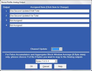
I would like to set my 4-20mA output module (20mAO4) to give an output of -50 MW to 50 MW. I am using 1600/5 CTs and 144000/120V PTs. How should I set it?
- First thing to know is that the mA output module can be set via secondary settings only for volts, amps and power. So using the CT and PT ratio, we need to convert to secondary the MW value that you desire. 50 MW is equal to 50,000,000 / (1600/5 x 14400/120) = 1302 w. Therefore, the high value (20 mA) = +1302 w while low value (4 mA) = -1302 w.
- To set the meter, using CommunicatorPQA® > Device profile > Ext I/O module > Assign each output to Watt Total
When I use Modbus I notice that most readings are in secondary values. How do I get to primary?
With the Nexus meters we mostly provide readings in secondary values. There are 2 ways to get to the primary values.
-
-
- You can multiply the secondary values by the CT and PT ratios. For voltage and current, you would have your system multiply by the PT ratio and CT ratio respectively. For example, if you hat a CT ratio of 1200/5 the ratio is 240. So, if you had 3.5A in the secondary IA register the primary current is 3.5X240 or 840A. For energy you need to multiply by both CT and PT ratio.
- The second method is to use the Custom Modbus mapping provided in the Nexus meters. Go into the profile for the meter and under general settings you will find a tab for Custom Modbus Map. You can define pretty much anything the meter reads or calculates in that map. You can use this to load Primary values into custom registers and then read Primary values.
-
CTs
What are the critical aspects to installing CTs correctly?
Primarily there are two critical things to get correct. First is the orientation of the CT. All CTs have a marking like a white dot on one side. This should always be installed facing the power source. For a typical installation on a building or where you want to measure energy to a load, you want the white dot facing the utility company. In all cases all CTs MUST be installed in the same orientation. Second you need to wire the CTs to the meter with the HI side of the CT connected to the HI side on the meter and the LO side to the LO terminals on the meter.
Should I use a shorting block for my CTs?
YES. You should always use a shorting block for your CTs unless you are working with a system that can easily be powered down for maintenance. The outputs of a CT should always be shorted together when the system is energized. If current is not allowed to flow the CTs will heat up very quickly and be damaged. Shorting blocks allow you to change out a meter without shutting down the system and will protect the CTs from being damaged.
What will happen if the CTs are installed incorrectly?
There are many symptoms you may see if the CTs are installed correctly. Mostly you will see things like negative watts in the Power readings. You may also see a reversal in the Energy Delivered and Energy Received registers. We can often look at the Phasor diagram and diagnose this issue. If you think you may have an issue send a phasor diagram to support@www.electroind.com and we will be happy to evaluate. We also need to know if you are connected as a Wye or Delta. Current and Voltage values will be normal since they only represent absolute values. If you have one CT oriented wrong, things like Total Energy will be in error because the energy in one phase will be subtracted from the energy in the other two phases.
How do I find the correct orientation and terminals/wires on my CTs?
All CTs should have a marking for orientation. Some have a white dot, some have a label others have some other marking. Make sure you check with the manufacturer if you are not sure. For most CTs with wires, there will be a white and black wire. In most but NOT ALL cases the white wire is the HI side and goes to the HI input on the meter. Black to LO. Again if you are not certain check with the supplier. For CTs with terminals, there should be a label on the HI terminal.
Contact Info
Monday through Friday, 8am – 8pm EST.
1800 Shames Drive
Westbbury, NY 11590
(877)346–3837 or 1–877–EIMETER
support@www.electroind.com
https://www.electroind.com/how-to-install-cts-for-eig-meters/
https://www.electroind.com/key-electrical-terms-know/
https://www.electroind.com/eig-software-fixes-current-transformer-reversals/
https://www.electroind.com/technical-support/how-to-videos/
https://www.youtube.com/watch?v=BfpiG_gOTDg
https://www.youtube.com/watch?v=jIXL0IHqQAw
https://www.youtube.com/watch?v=XTiIsF1D0Fc